
About one month ago I noticed one relay switch was flickering from time to time at the zone control board.
Narrow it down
The first step of debugging is to narrow the potential problem area down. Like any interesting (annoying) bugs, the problem doesn't happen all the time. So I waited a few days until it happened again. Then I tried a few things. One thing I tried was to remove the Nest Thermostat that's responsible for the heating zone. The clicking noise immediately stopped. Now in hindsight it seems obvious, because I learned so much about how HVAC system works from debugging the issue. But at the time, I knew pretty much nothing about HVAC system in general (I had no idea what those wires are for) and how the one we have is installed in my house — we just moved in not too long ago.
The most obvious next step to do is Googling. Not surprisingly, I found people had similar problems due to the lack of a C wire — common wire to my thermostat. I had no idea what C wire is. But there is this magic product called Nest Power Connector that's supposed to fix the no-C-wire-issue, without actually having to install a C wire. That sounds great. Ordered!
Nest Power Connector
So I had it delivered. The manual says nothing about how this thing works at all. But it has detailed steps of how to connect wires at the zone control. Sure, except it didn't work. It would call heat all the time even when the thermostat was not calling for heat. So far I had been doing the software engineering equivalent of stackoverflow-copy-paste. I just want the problem fixed. Time to sit down and learn about how HVAC actually works, and how is it setup at my home.
HVAC
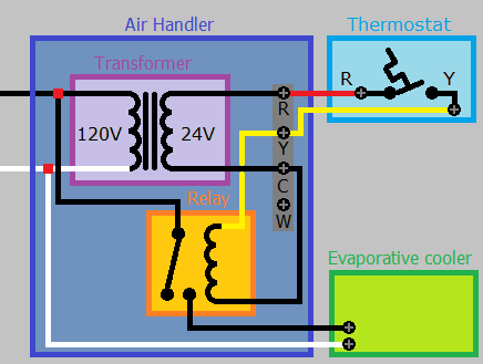
HVAC systems are actually very simple — well at least the thermostat controlling part of it is very simple. Using cooling as an example, thermostat has Rc and Y two wires connected to a condenser, powered with 24VAC. When a thermostat is not calling for cooling, there should be 24VAC between Rc and Y (they are disconnected). When Rc and Y are shorted, which happens when a thermostat is calling for cooling, there will be a 24VAC between Y and COM (common), which is used to energize a relay switch that completes the 120VAC condenser circuit (as shown in the diagram below).
Now let's measure the voltage.
Notice that the voltage is not stable, which explains the relay switch flickering.
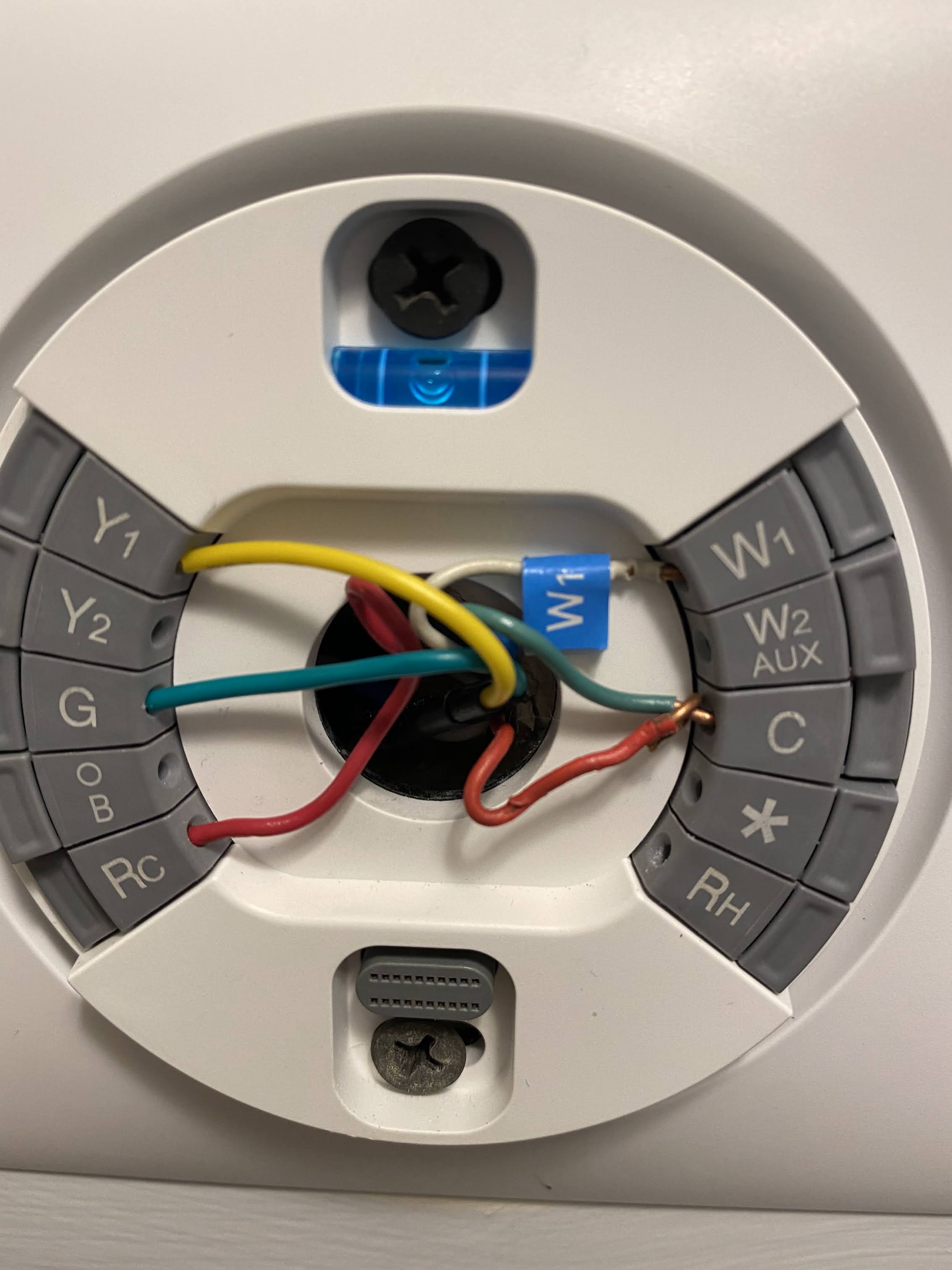
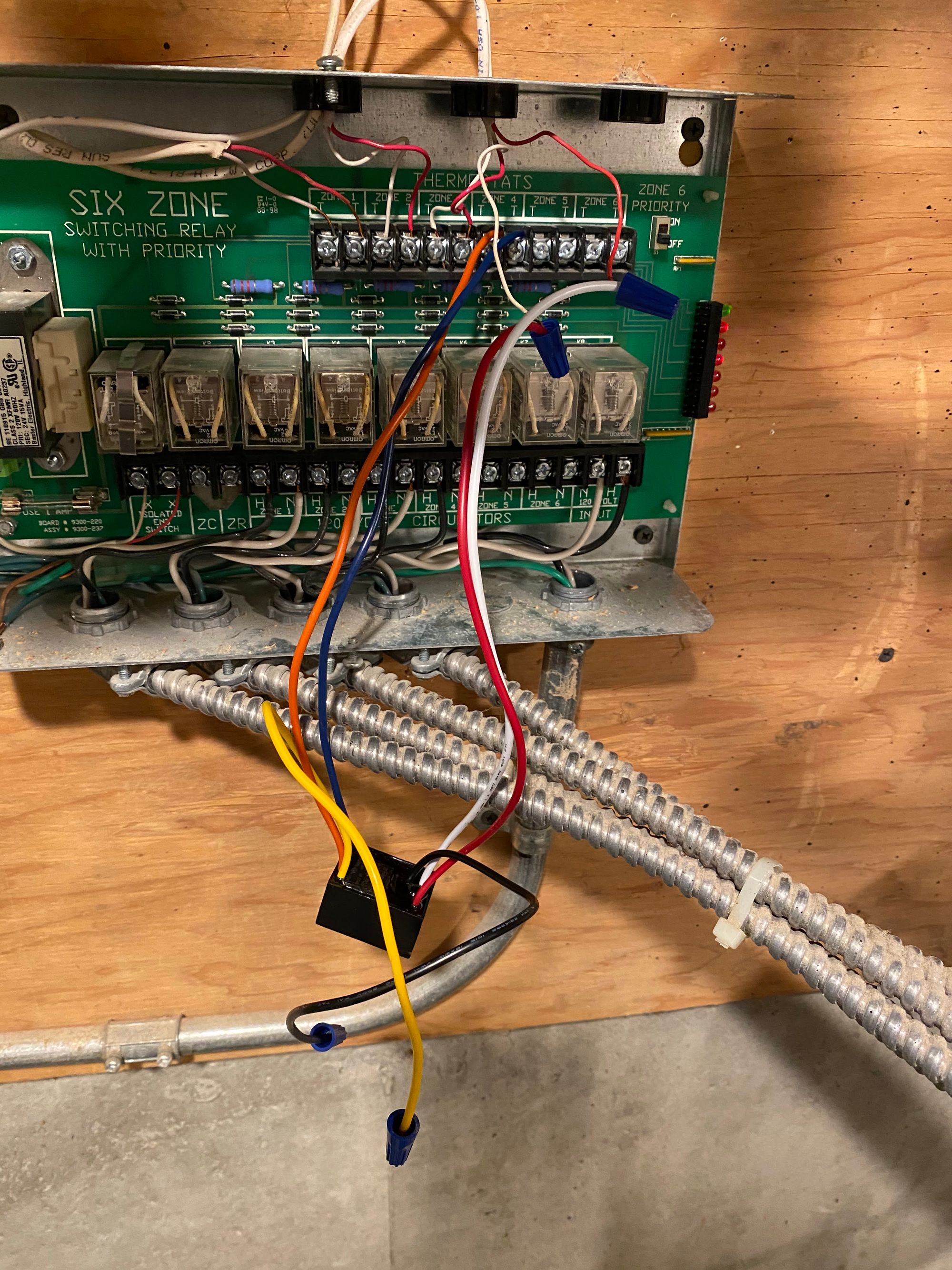
I followed wires in the house and learned about the HVAC setup in the house. There's one boiler with a zone control board that controls four zones in the basement. And there are three individual cooling unites, connected to each thermostats separately. The condenser that's connected to the problematic thermostat is on the second floor. The wires controlling the cooling unit are Rc, Y and G for power, cooling and fan respectively. The Nest is controlling one cooling unit nearby (on the second floor) and one heating unit far away (in the basement). Now here's the problem. The Nest had power from two separate systems (with two independent 24VAC transformers) – one for the AC, one for the boiler. Old school thermostat works by having a relay, energized by batteries usually, to short or disconnect Rh and W. That's why we can hear clicking sound from old school thermostats. I don't know exactly how Nest works internally, but for sure it's not just shorting and disconnecting Rh and W for controlling heat; otherwise you would have heard the same clicking sound from the Nest thermostat. To call heat, the thermostat needs to put 24VAC between W and COM at the zone control board, which is used to energize the relay switch that kick-starts the 120VAC boiler. When it's not calling for heat, the voltage between W and COM should be zero. How would Nest put zero voltage between W and COM without a physical relay inside? It doesn't have a common wire. Well the best it can do is to put 24 VAC between Rh and W at the boiler, hoping that it will bring voltage between W and COM to zero. Since Nest is powered by AC, this 24 VAC, used to make voltage between W and COM zero, has to come from the AC transformer (not the heating zone control transformer). That is a problem. These are two different transformers. There's virtually no guarantee that they will output the exactly same sine waves, synchronized. If there's a small output voltage difference, or tiny phase shift, there will be a voltage between W and COM, and the relay switch will flicker. Now we understand the problem; but we still have this super fun game to play – fixing the problem without adding physical wires from the basement to the second floor.
Install a C wire
First, let's add a solid C wire. Venstar Add-a-wire can add a C wire without adding a new wire from zone control all the way to thermostat. (I am not associated with the product in anyway other than being a happy customer.) There are plenty of videos on the internet that explains how to install it. The idea is that you will multiplex two signals e.g. Y and G over a single physical wire behind your wall, which frees up one physical wire that can be used for the C-wire. But how does it work exactly? I found this answer on the internet.
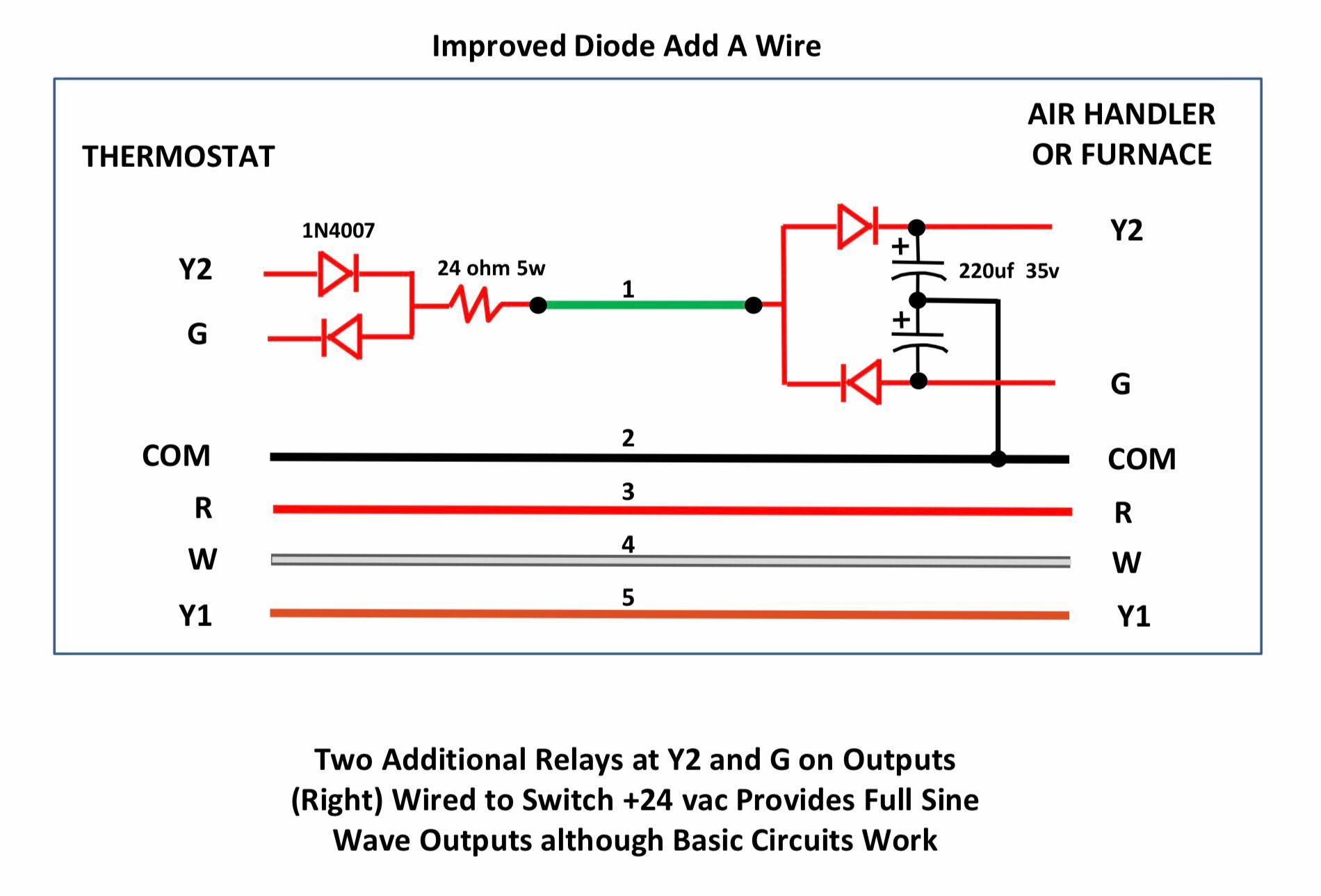
The diagram left out Rc which energizes the 24VAC control signal. You can imagine that that Rc is connected to G and Y2 on both sides. When the thermostat is trying to call cooling (Y), it will complete the Y2 circuit. But if we simply multiplex over two pairs of diodes, you would only get half sine wave outputs for Y and G. To get full sign wave at the output, that drives the relay switch, the add-a-wire box installed in the condenser (right hand side), has two additional replay switches. So when Y2 is energized, the relay switch will close, Y2 output will get the full sine wave from COM (common). Basically, Y2 and G now only sends signals to the add-a-wire control, which then sends full sine wave output from COM to the actual relay switch at the condenser.
After it's installed, the problem went away for about a week. The theory is that the basement heating unit and the second floor AC share common, which seems pretty reasonable. Then it helps calibrate the output voltages of the two transformers to be 24VAC. But it doesn't help solve the problem if there's a tiny phase difference between the two transformers. That's why after about a week, the flickering issue happened again.
Install an isolation relay
Given the problem is caused entirely by having two transformers, what if we just remove one entirely? I found this helpful post on Reddit, which suggests adding an isolation relay on boiler. The idea is that Nest can be powered entirely on the AC transformer, and we can remove the Rh from the thermostat entirely. Ecobee has the same idea posted as well.
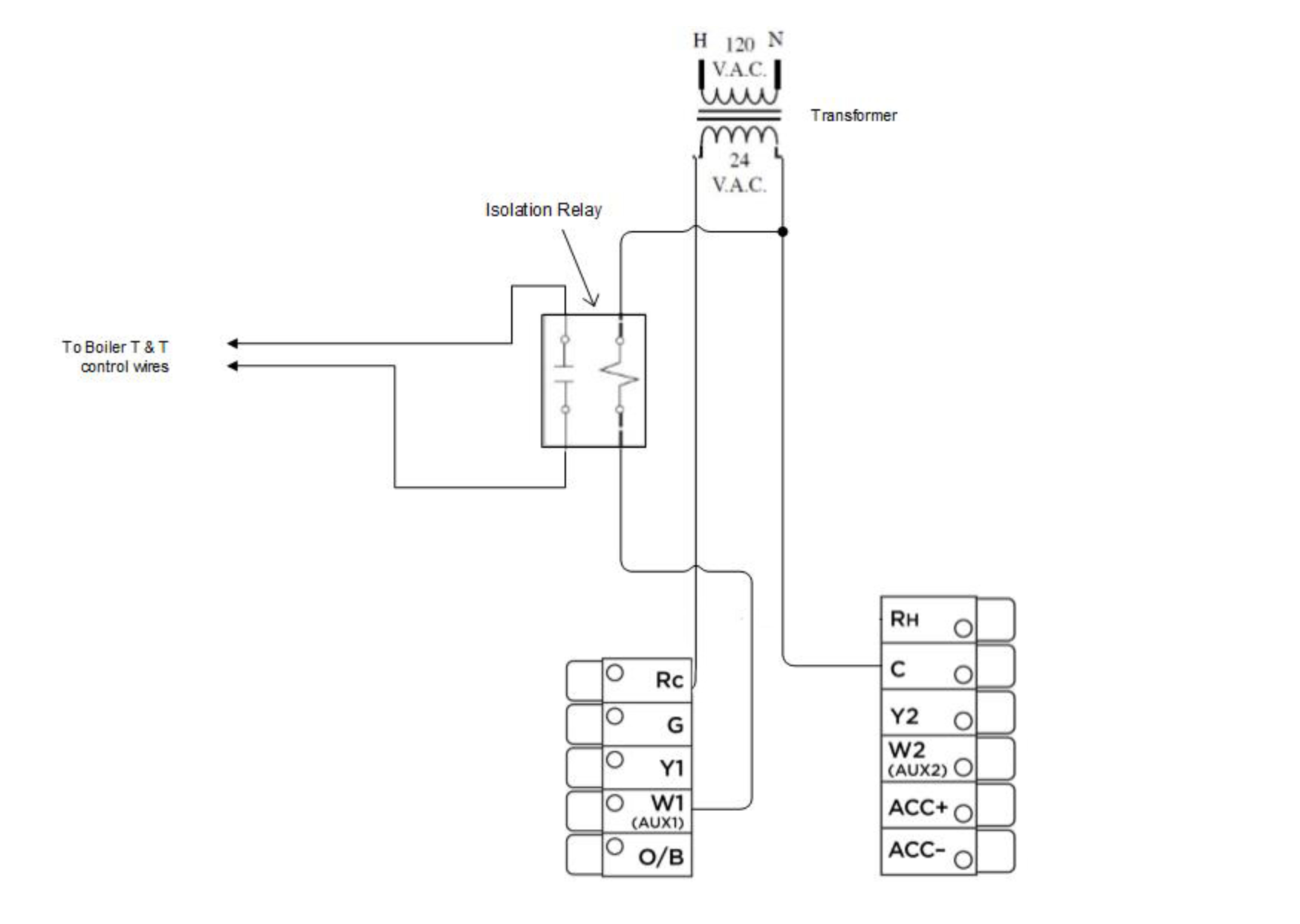
When the thermostat tries to call heat, it will put 24VAC on W1 (relative to C), As a result, it will energize the isolation relay, which physically shorts T & T terminals at the boiler. This is a great idea, as it guarantees to solve the problem entirely. However, it requires the isolation relay to be connected to C (the C from AC). My boiler is in the basement, and the AC is on the second floor. Then it dawned on me that I could repurpose the no-longer-needed Rh wire to send C all the way from the second floor to my basement.
The final result looks like this. And it works beautifully.
Debugging a system is probably the best way to learn how it actually works.
Parts used — unaffiliated
PAM-1 isolation relay https://www.amazon.com/gp/product/B004KNPRBK/ref=ppx_yo_dt_b_asin_title_o00_s00?ie=UTF8&psc=1
Venstar add-a-wire https://www.amazon.com/gp/product/B01IF3QXMC/ref=ppx_yo_dt_b_asin_title_o05_s00?ie=UTF8&psc=1